Scan to CAD to Print · Workflow
Scan to CAD to Print: How a Real Object Becomes a New Part
A physical object goes in; a manufacturable part comes out. Here's the four-stage pipeline that gets it there — and why the CAD step is what makes it powerful.
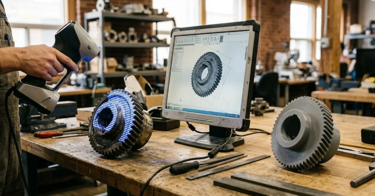
You have a part in your hand — a worn bracket, a legacy component, a shape someone made by feel — and no drawings for it anywhere. How do you turn that into something you can remake, improve, and produce on demand? That's exactly what the scan-to-CAD-to-print workflow is for, and it runs straight through 3D scanning, CAD, and manufacturing as one connected pipeline.
The idea is simple: capture the object as it really is, rebuild it as an editable digital model, then make the part. Each stage hands a specific file to the next, and the payoff is that you end up with a part you can actually change — not just a photocopy in plastic. Below is the plain version of how it works. If you'd rather just send us the object, we'll take it from there — but here's the pipeline.
Short answer
It's a four-stage pipeline: scan the object into a point cloud, mesh it into a clean STL, model it as editable solid CAD (STEP), then make the part by printing or machining. Scanning captures reality; CAD makes it changeable — so you finish with a part you can edit, improve, and reproduce, even when no drawings ever existed.
01The four-stage pipeline
Every scan-to-part job follows the same four moves. Each one produces a specific output that becomes the input for the next — that hand-off is what keeps the whole thing accurate end to end.
-
01
Capture
3D-scan the object from every angle, recording its real surface as millions of measured points.
→ Point cloud -
02
Mesh
Align the scan passes, clean the noise, and close any gaps into one watertight surface.
→ STL mesh -
03
Model
Rebuild the mesh as true solid CAD — real edges, faces, and dimensions you can edit.
→ STEP file -
04
Make
Manufacture the part from the model — 3D printed or CNC machined, in the right material.
→ Finished part
02The files that connect it
Each stage speaks in a different file format, and the data gets richer as it moves down the line — from raw measured points, to a printable surface, to a fully editable model, to a physical part.
You can stop early if all you need is a straight copy — a clean STL prints as-is. But the moment you want to change anything, you need the stage most people skip: real CAD.
03STL vs STEP: why the CAD step matters
This is the distinction that trips people up, and it's the heart of the whole workflow. An STL and a STEP might describe the same shape, but they are not the same thing — and only one of them lets you actually work with the part.
| STL | STEP | |
|---|---|---|
| What it is | Triangle mesh (surface skin) | Solid CAD model |
| Editable? | No — fixed shape | Yes — dimensions & features |
| Best for | Printing a copy as-is | Redesign, machining, changes |
A scan tells you what a part is. CAD is what lets you decide what it should be.
That's why we rebuild the mesh into a proper solid model rather than handing back a raw scan. With real CAD, the part isn't frozen — it's a starting point you can thicken, reinforce, resize, or adapt before a single one is made.
04Where this workflow earns its keep
The pipeline shines whenever the physical object exists but the digital model doesn't. A few of the most common reasons parts come through our door this way: reproducing an obsolete or discontinued part no one sells anymore; creating a custom fit around an existing surface, like a housing or mount; improving a design that only ever existed as a physical prototype; and digitizing handmade or sculpted work so it can be reproduced consistently.
In every one of those, the value isn't just the copy — it's having the part as editable CAD afterward. Because scanning, modelling, and manufacturing all happen under one roof, the object never has to leave the pipeline to get from your hand to a finished part.
Have an object but no drawings?
Send it our way — we'll scan it, rebuild it in CAD, and make the part, better than the original if you want.
Start a quoteFrequently asked questions
// tap a question to expand
What is the scan-to-CAD-to-print workflow?
It's the process of capturing a physical object with a 3D scanner, converting that scan into editable CAD, and then manufacturing a new part from it by 3D printing or CNC machining. It turns a real object into a digital model you can change and reproduce.
What's the difference between STL and STEP?
An STL is a triangle mesh — a fixed surface skin that's good for printing as-is but can't easily be edited. A STEP is a solid CAD model with real dimensions and features, so it can be modified, machined from, and used for redesign.
Can you 3D print straight from a scan?
Sometimes. A cleaned, watertight mesh (STL) can be printed directly for a straight copy. But if you need to change dimensions, fix a flaw, or machine the part, the scan has to be rebuilt as CAD first.
Do I need the original drawings?
No — that's the whole point. Scanning captures the geometry of a part even when no drawings or CAD exist, which is how obsolete, legacy, or one-off parts get reproduced.
How accurate is the final part?
It depends on the scan and the manufacturing method. The scan sets the reference geometry and the chosen process holds the tolerance, so accuracy is matched to what the part actually needs.
Can you improve the part, not just copy it?
Yes. Once the object is rebuilt as editable CAD, we can strengthen, lighten, or adapt the design before manufacturing — so you can end up with a better part than the original, not just a duplicate.