SLS 3D Printing · Nylon Parts · Complete Guide
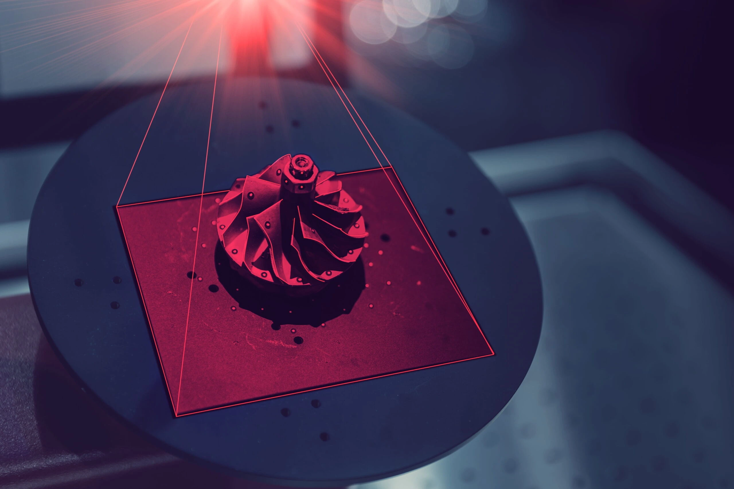
Selective Laser Sintering (SLS) is a powder-bed 3D printing process that uses heat and laser energy to fuse polymer powder into durable parts, one layer at a time. Because surrounding powder supports the build, SLS can produce complex geometry without conventional support structures.
When a component needs to survive real handling, repeated assembly or mechanical use, SLS 3D printing is often worth considering. It combines durable engineering plastics with a powder-based process that can manufacture complex parts, nested batches and functional geometries that may be difficult to produce efficiently with filament or resin printing.
SLS is used for much more than visual prototypes. It can produce functional prototypes, brackets, housings, ducts, snap-fit assemblies, jigs, fixtures, replacement parts and low-volume end-use components. The correct decision still depends on the application: material behaviour, geometry, finish, tolerances, quantity, operating environment and budget all matter.
This guide explains how SLS works, what makes SLS nylon useful, how it compares with FDM and SLA, what to consider when designing a part and what information to send when requesting a quote from a professional 3D printing service in Montreal.
Short answer
SLS 3D printing uses a laser to fuse thin layers of polymer powder inside a heated build chamber. Unfused powder supports the parts during printing, allowing complex nylon geometry without separate support structures. It is commonly chosen for functional prototypes, durable end-use parts and small production batches.
01What is SLS 3D printing?
SLS stands for Selective Laser Sintering. It belongs to the powder-bed fusion family of additive manufacturing processes. Instead of extruding filament through a nozzle or curing liquid resin in a vat, an SLS machine spreads a thin layer of polymer powder and selectively fuses the cross-section of each part.
After one layer is fused, the build platform moves, another layer of powder is applied and the process repeats. The finished components remain surrounded by loose powder until the build cools and the parts are unpacked.
The loose powder performs an important second job: it supports overhangs, internal features and nearby components during the build. This eliminates many of the support structures required by other 3D printing processes and gives designers more freedom to consolidate parts or place several components throughout the build volume.
SLS is a process, not a material. Nylon is the material family most closely associated with SLS, but the exact powder formulation affects stiffness, toughness, flexibility, temperature behaviour, finish and cost.
02How does selective laser sintering work?
A professional SLS project begins before the machine starts. The CAD model, orientation, nesting strategy, material and finishing requirements all affect the result.
Review and prepare the model
The part is checked for manufacturability, wall thickness, clearances, enclosed powder, orientation-sensitive features and other project requirements. Multiple components can be arranged within the build volume.
Preheat the powder bed
The build chamber is heated close to the material’s processing temperature. This reduces the amount of additional energy the laser must apply and helps manage thermal behaviour during printing.
Spread and fuse each layer
A recoating system spreads a thin layer of powder. The laser traces the required cross-section and fuses selected areas. The platform then moves and the cycle repeats until the build is complete.
Cool the completed build
The powder bed must cool in a controlled way before unpacking. Cooling is part of the production cycle and helps reduce distortion or damage that could occur if hot parts were removed too early.
Unpack and clean the parts
Parts are removed from the powder cake and loose material is cleaned from exterior surfaces, holes and internal features. Additional finishing may be specified according to appearance and function.
Inspect and deliver
Finished components are reviewed against the project requirements. Validated files can then support another prototype iteration or future production runs.
03Advantages and limitations of SLS 3D printing
No manufacturing process is best for every component. Understanding both sides of SLS helps prevent an attractive technology from being used for the wrong reason.
Why engineers choose SLS
- No conventional support structures
- Complex and enclosed geometry
- Durable engineering-grade nylon options
- Functional snap fits and moving assemblies
- Efficient build-volume nesting
- Prototype-to-production flexibility
- No dedicated injection mould required
What to consider
- Natural powdery or lightly textured surface
- Cooling adds time to the production cycle
- Loose powder needs an exit from cavities
- Thin broad geometry may be prone to warping
- Fine cosmetic detail may favour SLA
- Machining may suit the tightest interfaces
- Material options differ by equipment
SLS can reduce assembly by combining features that would otherwise require several manufactured pieces. However, consolidated geometry must still allow loose powder to be removed and the finished component to be inspected, serviced and used safely.
04SLS materials and nylon options
Material selection should begin with what the component must do, not with a material name alone. Loads, impact, flexibility, temperature, chemicals, moisture, surface requirements and regulatory needs should be reviewed before production.
PA12 nylon
PA12 is a widely used SLS material because it offers a practical balance of strength, toughness, dimensional stability and detail. It is commonly considered for housings, brackets, ducts, jigs, fixtures, clips, snap-fit parts and repeat functional components.
PA11 nylon
PA11 is often selected where ductility, impact performance or repeated flexing is more important. Availability, finish and mechanical properties depend on the specific powder and production system.
Glass-filled nylon
Glass-filled nylon can provide greater stiffness and improved dimensional behaviour for certain applications, but added stiffness may come with different impact or flex characteristics. It should be selected around the actual load case.
Flexible powders
Some powder-bed systems process flexible materials such as TPU for seals, protective components and flexible geometries. Hardness, rebound, surface finish and dimensional expectations should be confirmed for the specific material.
Material availability changes. Ask 3DRM Tech which SLS powder, colour and finishing options are available for your project rather than designing around an assumed datasheet.
05SLS strength, accuracy and surface finish
Are SLS parts strong?
SLS nylon parts can be strong enough for many functional prototypes and end-use applications. Actual performance depends on the selected material, geometry, wall thickness, orientation, machine settings, environmental conditions and the type and direction of the applied load.
Compared with standard FDM parts, SLS often provides more uniform behaviour in different directions because it does not rely on extruded roads in the same way. That does not mean every SLS part is perfectly isotropic or that it will match an injection-moulded or machined material in every application. Functional requirements should be reviewed against material data and tested when failure would be costly.
How accurate is SLS?
Accuracy is influenced by overall size, geometry, wall thickness, feature location, thermal behaviour and process setup. Thin broad surfaces and abrupt thickness changes may behave differently from compact, well-supported geometry. If a hole, fit or interface is critical, identify it when requesting the quote so the model and inspection approach can be planned appropriately.
What surface finish does SLS produce?
Standard SLS parts normally have a uniform matte, lightly textured surface. They do not carry conventional support marks, but they are not as naturally smooth or glossy as many SLA resin parts. Depending on the project, parts may be cleaned, tumbled, dyed, coated, sealed, painted or machined in selected areas.
06Common applications for SLS nylon parts
SLS is valuable where complexity and function matter more than a perfectly smooth mould-like surface. Typical applications include:
A prototype should test the characteristics that matter in the real application. A component that looks correct may still need testing for assembly, repeated use, impact, heat, chemicals, moisture, fatigue or outdoor exposure.
Test before production Explore rapid prototyping services in Montreal →07SLS vs. FDM, SLA and injection moulding
The right manufacturing route depends on the entire requirement. The following comparison is a starting point rather than a substitute for reviewing the actual CAD and application.
// quick process comparison
| Process | Typical strength | Geometry and finish | Often chosen for |
|---|---|---|---|
| SLS | Durable engineering nylon options | Complex unsupported geometry; matte textured finish | Functional prototypes, end-use parts and nested batches |
| FDM | Strong thermoplastics with orientation-dependent behaviour | Practical geometry; visible layer lines and support considerations | Cost-effective prototypes, tooling and larger functional parts |
| SLA | Material-dependent; many resins prioritize detail or finish | Fine detail and smooth surfaces | Visual models, master patterns and detailed prototypes |
| Injection moulding | Broad production-material options | Repeatable moulded finish after tooling | Higher volumes that justify mould design and tooling |
SLS vs. FDM
FDM is often economical for one-off parts, larger components and straightforward functional geometry. SLS may be preferable for complex shapes, nested quantities, snap fits and parts where eliminating conventional supports improves design freedom. Part size, finish, material and batch economics can shift the decision.
SLS vs. SLA
SLA is generally selected when fine visual detail and smooth surfaces are the priority. SLS is more commonly associated with durable nylon parts and production-oriented functional geometry. Specialized resins can be highly capable, so the application and material datasheet still matter.
SLS vs. injection moulding
SLS avoids dedicated mould tooling and allows fast design changes, customization and lower-volume production. Injection moulding can provide much lower unit economics at sufficient scale, but it requires tooling investment and a more stable design. SLS is often useful for pilot runs, bridge production and products whose demand does not yet justify a mould.
Process selection Read the complete FDM vs. SLS vs. SLA comparison →08How to design parts for SLS 3D printing
SLS offers substantial geometric freedom, but it does not remove the need for design for manufacturing. Machine, material and application-specific guidelines should be confirmed before finalizing production geometry.
Use suitable wall thickness
Walls must be thick enough to print, clean and survive service. Very thin walls may flex, distort or break during unpacking. Required thickness varies with material, wall length, geometry and load.
Allow clearance between moving or mating features
Interlocking and moving assemblies can sometimes be printed together, but insufficient clearance may cause features to fuse or trap powder. Fits should reflect the machine, orientation, material and intended motion.
Provide powder escape paths
Hollow parts and internal channels need accessible openings so loose powder can be removed. An enclosed cavity may trap material, add weight and make cleaning or inspection impossible.
Manage broad, thin surfaces
Large flat areas with little thickness can be sensitive to thermal distortion. Ribs, curvature, thickness changes or a different orientation may help, but the best solution depends on the design.
Define critical holes, threads and interfaces
Small holes, threads and precision mating surfaces may require compensation, secondary machining, inserts or another production strategy. Mark critical dimensions clearly instead of assuming the same tolerance is needed everywhere.
Use readable text and durable details
Embossed or engraved text and small features must be sized for the chosen process and finishing method. Details that appear in CAD can soften during printing or finishing if they are too fine.
If the model is still being developed, 3DRM Tech’s CAD design service can help prepare geometry around the intended printing and manufacturing route.
09Is SLS suitable for low-volume production?
Yes, when the material, geometry, performance and economics fit the application. SLS can produce multiple parts throughout the build volume without dedicated mould tooling. That makes it useful for pilot runs, bridge production, replacement parts, customized components and ongoing batches with moderate demand.
SLS may provide particular value when:
- The quantity is too low to justify injection-mould tooling
- The design may still change between batches
- Several part variants are required
- Complex geometry would increase conventional manufacturing cost
- Replacement components are needed only when equipment fails
- A production bridge is needed while tooling is being prepared
Low-volume production still requires revision control, repeatable files, defined materials, agreed finishing and appropriate quality checks. A validated prototype is not automatically a production plan; it is the foundation for one.
Prototype to repeat parts Explore low-volume manufacturing with 3DRM Tech →10How much does SLS 3D printing cost?
SLS pricing is project-specific. Part size alone does not determine cost because the complete build, material use, packing strategy, cooling, unpacking, cleaning and finishing all affect production.
Common cost factors include:
- Part volume and bounding-box dimensions
- Material and colour requirements
- Number of parts and how they can be nested
- Wall thickness and amount of enclosed powder
- Geometry, orientation and risk of distortion
- Cleaning access for internal channels and cavities
- Required dimensional verification
- Surface finishing, dyeing, coating or secondary machining
- Packaging, delivery and project timing
Unit pricing may improve when several parts share a build efficiently, but quantity alone does not guarantee a lower price. A compact part that nests well can behave differently from a large hollow component that occupies substantial build volume.
3DRM Tech currently has no fixed minimum part quantity, while a $500 minimum overall project value applies. SLS projects and schedules are quoted individually after the team reviews the CAD, quantity, material and application.
11What should you send for an SLS quote?
You do not need to select the process before contacting 3DRM Tech. If SLS is not the right route, the team can compare FDM, SLA, CNC or another suitable manufacturing option around the actual requirement.
If no production-ready model exists, send a drawing, sketch, reference part, scan or description of what you need. CAD development can be included before printing.
Need durable nylon parts?
Send your CAD file, quantity and application requirements. 3DRM Tech will review the geometry and recommend SLS or another practical manufacturing process for your project.
Request an SLS project quote →12Frequently asked questions about SLS
// common questions, answered
What does SLS stand for in 3D printing?
SLS stands for Selective Laser Sintering. It is a powder-bed fusion process in which laser energy fuses selected areas of polymer powder to build a part layer by layer.
How does SLS 3D printing work?
An SLS machine spreads a thin layer of powder inside a heated build chamber. A laser fuses the cross-section of each part, the platform moves and another layer is spread. The cycle repeats until the build is finished, cooled, unpacked and cleaned.
Does SLS 3D printing require supports?
SLS does not normally require conventional printed support structures because loose powder surrounds and supports the components during the build. Designs must still allow trapped powder to be removed.
What materials are used for SLS printing?
Nylon powders such as PA12 and PA11 are widely associated with SLS. Glass-filled nylon and flexible powders may also be available. The correct material and current availability should be confirmed for each project.
Are SLS nylon parts strong?
SLS nylon can be suitable for many functional prototypes and end-use components. Actual performance depends on the material, geometry, wall thickness, process setup, operating environment and applied loads. Critical applications should be validated through appropriate engineering and testing.
Is SLS stronger than FDM?
Not in every situation. SLS often provides more uniform multi-directional behaviour and handles complex nylon geometry well, while FDM offers a broad range of strong thermoplastics and can be economical for larger or straightforward parts. Compare the specific materials, geometry and load case.
What surface finish do SLS parts have?
Standard SLS parts typically have a uniform matte, lightly textured surface. Additional cleaning, tumbling, dyeing, coating, sealing, painting or selective machining may be available depending on the part and desired result.
Can SLS produce moving or interlocking parts?
It can produce some moving or interlocking assemblies in one build because loose powder supports the geometry. Sufficient clearance and powder-removal access are essential, and the design should be reviewed for the specific machine and material.
Can SLS be used for finished production parts?
Yes. SLS can support low-volume end-use production when the selected material, geometry, finish, tolerances and testing requirements fit the application. It is also useful for pilot runs, bridge production and replacement parts.
How accurate is SLS 3D printing?
Accuracy depends on the equipment, material, geometry, size, wall thickness, thermal behaviour and process setup. Identify critical dimensions and fits before quoting so the team can review whether SLS and any secondary operations can meet the requirement.
How long does SLS printing take?
Timing includes file review, build scheduling, printing, controlled cooling, unpacking, cleaning, finishing and inspection. 3DRM Tech quotes SLS schedules individually because part size, quantity, material and finishing requirements vary.
What file should I send for an SLS quote?
Send a STEP, STL or the best available CAD file along with quantity, intended use, material needs, finish expectations and critical dimensions. If no suitable CAD exists, send a sketch, drawing, photograph, scan or project description for review.